Do you need to control up to 32 LCD displays using just one data line and without writing any source code?
Now it is possible with SXLCD board!
What is SXLCD?
SXLCD board is an hardware designed to allow you to control an LCD display with an Hitachi 44780 interface,
using just one serial line (both TTL and RS232).
A very interesting feature is the possibility to connect several SXLCD boards (up to 32) on a single serial line and,
thanks to the software addressing, to send commands independently to each single module or to a group of modules.
The board allows, not only to write on the display, but also to regulate the backlight in order to control power
consumption according to your own needs.
SXLCD board so has multiple advantages such as the severe simplification in writing program and firmware
for microcontrollers or the I/O lines great saving, thanks to the use of serial communication.
Alternatively SXLCD board may be used also as totally transparent hardware interface, since a connector that carries
all the display control signals is available: in this case the advantage in using the interface is that all the
electronic equipment for power supply, backlight and communication is already onboard and also LCD signals are
available on an easily mountable 2x5 connector.
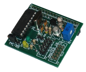
Hardware description
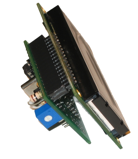
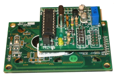
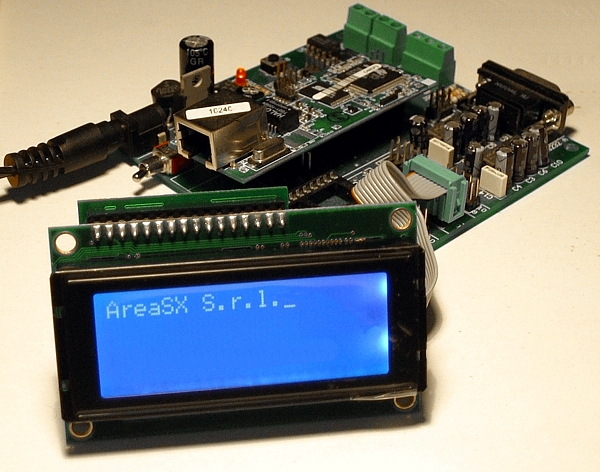
Physically SXLCD is a very small board (41x45mm) and it is equipped on one side with a double 16 pins connector
suitable for a "sandwich way" link of a LCD display; on the other side there is the control circuits and some
connectors and jumpers to carry power supply, serial and configuration signals.
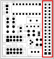
JP6 and JP7 connectors
The 16 pins double connector, named with JP6 and JP7, has been designed for LCD connection with two different
kind of pin out. This way the board can be used with a large number of displays, allowing to chose the one that
better fits your own needs. Area SX gives a wide range of LCD display with different topology: 8x2, 16x2, 20x2, 20x4.
In the following table you will find the connector pin out where the display is connected:
| Pin |
JP6 Connector |
JP7 Connector |
| 1 |
GND |
+VBL |
| 2 |
+VLCD |
-VBL |
| 3 |
VO (contrast) |
GND |
| 4 |
RS |
+VLCD |
| 5 |
GND |
VO (contrast) |
| 6 |
EN |
RS |
| 7 |
NC |
GND |
| 8 |
NC |
EN |
| 9 |
NC |
NC |
| 10 |
NC |
NC |
| 11 |
D0 |
NC |
| 12 |
D1 |
NC |
| 13 |
D2 |
D0 |
| 14 |
D3 |
D1 |
| 15 |
+VBL |
D2 |
| 16 |
-VBL |
D3 |
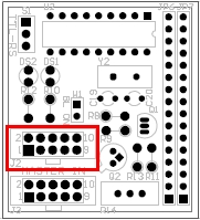
Connettori di segnale J2 e J3
The 10 pin connector named J2, form which SXLCD receives serial signal and power supply,
is compliant with many boards produced by Area SX such as SX3000, SX18 plus FOX and SX18 plus BasicX.
In the following table you will find J2 connector pin out:
| J2 pin |
Signal |
| 1 |
RX input |
| 2 -3- 4 - 5 - 6 - 7 -8 |
NC |
| 9 |
Vcc +5V |
| 10 |
GND |
Next to J2 connector, there is a second 10 pins connector named J3 where all display signals are
directly carried out.
To use directly this interface you need to remove the U2 microcontroller from its slot
to avoid short-circuits with the port where display lines are connected.
In the following table you will find J3 connector pin out:
| J3 pin |
Signal |
| 1 |
D0 |
| 2 |
D1 |
| 3 |
D2 |
| 4 |
D3 |
| 5 |
RS |
| 6 |
EN |
| 7 |
BL BackLight |
| 8 |
NC |
| 9 |
Vcc +5V |
| 10 |
GND |
Backlight control
Display backlight may be controlled both via serial commands and via hardware.
But with hardware control, it is only possible to force backlight to be always on at maximum brightness or always off.
Backlight control through serial commands is much more interesting: in fact this way it is possible to fine
adjust backlight level allowing to optimize brightness according to power consumption and,
on the other hand, to realize attractive effects for users such as "progressive lighting".
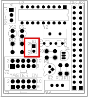
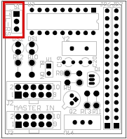
Configuration jumpers
The board has two configuration jumpres named W1 and S1.
-
Jumper W1, if closet, allows to force backlight to remain always on
-
Jumper S1 allows to chose serial voltage level. Two levels are available:
serial TTL (levels 0, +5V), that allows to connect SXLCD directly to the serial port of every microcontroller
(e.g. PIC, Rabbit , BasicX, Fox);
serial RS232 (-12V,+12V), that allows to connect on J2 pin 1 a signal with RS232 voltage level,
e.g. pin 3 of a PC serial port, without any need of other circuits.
Software protocol
SXLCD board uses a serial protocol with 19200bps baudrate, 8 data bit, no parity and 1 stop bit.
Communication is one way, from "master" (PC or microprocessor that drives the board) towards SXLCD;
there is no response to sent commands.
This way it is possible to connect on the serial line more then one display (up to 32) and each of
them can be driven separately from the others.
All the commands to be sent to SXLCD are at least 6 bytes long, except for the write commands because
the text characters to be displayed must be take in account. The following table shows commands structure:
| Byte 1 |
Byte 2 |
Byte 3 |
Byte 4 |
Byte 5 |
[Byte 6...N-1] |
Byte N |
| 0x3E '(>)' |
Address |
Command |
Data 1 |
Data 2 |
[Text] |
0x00 (end of packet) |
All the commands start with the character '>' followed by the SXLCD board address,
that can have a value between 1 and 254. 255 (0xFF) address is a broadcast one and it is usefull
to send the same command to all the board connected on the serial bus, no matter their own address.
The following byte, after the address (byte number 3), is the one that specifies the kind of operation
to perform on the display. The following table shows the complete list of the available commands:
| Command |
Description |
| 0x01 |
Clean the display |
| 0x02 |
Write the sent text starting from the current cursor position |
| 0x03 |
Write the sent text starting from the specified position |
| 0x04 |
Set backlight brightness |
| 0x05 |
Set SXLCD board address |
| 0x06 |
Set cursor visualization mode |
| 0x07 |
Set display main parameters |
| 0x08 |
Set automatic new line mode |
Bytes that follow the command (byte 4 and 5) specify optional parameters; if the command doesn't need them,
they have to set to 0x00.
The following bytes may or not be present, according to data needed by the specific command:
last byte must always be null (0x00) to signal the end of data packet to SXLCD.
In the following section, each command is analyzed in detail.
COMMAND 0x01: Clean the display
It cleans all the rows currently showed on the display
| Byte 1 |
Byte 2 |
Byte 3 |
Byte 4 |
Byte 5 |
Byte 6 |
| 0x3E |
Address |
0x01 |
0x00 |
0x00 |
0x00 |
COMMAND 0x02: Write the sent text starting from the current cursor position
It writes the sent text starting from the position where last text ended.
If message text reaches display right limit, then the behaviour will be determined
by "new line" setting (see command 0x08)
| Byte 1 |
Byte 2 |
Byte 3 |
Byte 4 |
Byte 5 |
Byte 6...N-1 |
Byte N |
| 0x3E |
Address |
0x02 |
0x00 |
0x00 |
Text |
0x00 |
COMMAND 0x03: Write the sent text starting from the specified position
It writes the sent text stariting from the specified position using byte 4 and 5.
Byte 4 means the column number where writing will start and it may have values between 0 and
the display supported maximum number of characters.
Byte 5 means the row number and its values go from 0 (first row) to the display supported maximum number of rows minus 1.
For a 4 rows display, last row will be number 3.
| Byte 1 |
Byte 2 |
Byte 3 |
Byte 4 |
Byte 5 |
Byte 6...N-1 |
Byte N |
| 0x3E |
Address |
0x03 |
Position X |
Position Y |
Text |
0x00 |
COMMAND 0x4: Set backlight brightness
It sets display backlight level.
This command allows to define backlight brightness level. The level to be set, is sent using byte 4 and it may have
values from 0 (backlight off) up to 255 (backlight top brightness). Brightness may change continuously using middle
range values, allowing the best compromise between power consumption and visibility.
| Byte 1 |
Byte 2 |
Byte 3 |
Byte 4 |
Byte 5 |
Byte 6 |
| 0x3E |
Address |
0x04 |
Brightness |
0x00 |
0x00 |
COMMAND 0x5: Set SXLCD board address
It allows to set SXLCD software address. It is possible to send this command both to a single board
(if its current address is known) or to all the boards connected to serial line, using broadcast address.
This way it is possible to set the address of one single board (e.g. the current address is no more known):
the operation must be carried out detaching from the serial bus all the boards except for the one you want to configure.
New address specified by Byte 4 may have a value between 1 and 254 (0x1 - 0xFE hexadecimal).
Address setting is permanently stored and it is retained when power supply is turned off.
| Byte 1 |
Byte 2 |
Byte 3 |
Byte 4 |
Byte 5 |
Byte 6 |
| 0x3E |
Address |
0x05 |
New Address |
0x00 |
0x00 |
COMMAND 0x6: Set cursor visualization mode
It selects cursor visualization mode on the display.
Available options to insert in Byte 4 are:
- 0x00 not visible cursor
- 0x01 fixed cursor
- 0x02 blinking cursor
| Byte 1 |
Byte 2 |
Byte 3 |
Byte 4 |
Byte 5 |
Byte 6 |
| 0x3E |
Address |
0x06 |
Mode |
0x00 |
0x00 |
COMMAND 0x07: Set display main parameters
This command allows to set main parameters of the LCD display connected to the board.
The command must be executed with 5 parameters representing:
- Byte 4: Display row 1 address
- Byte 5: Display row 2 address
- Byte 6: Display row 3 address (if not available send 0xFF)
- Byte 7: Display row 4 address (if not available send 0xFF)
- Byte 8: Display rows and columns number. Format is YYYXXXXX, where YYY = rows number, XXXXX = columns number
Command is permanently stored so it must be executed just one time.
| Byte 1 |
Byte 2 |
Byte 3 |
Byte 4 |
Byte 5 |
Byte 6 |
Byte 7 |
Byte 8 |
Byte 9 |
| 0x3E |
Address |
0x07 |
Row 1 address |
Row 2 address |
Row 3 address |
Row 4 address |
Rows and columns number |
0x00 |
COMMAND 0x08: Set "automatic new line" mode
This command allows to define the mode to manage display "new line".
Byte 4 may have value 0x00 ("new line" disabled) or 0x01 ("new line" enabled).
When "new line" is enabled, if the text to be written that reaches display right edge,
then the its exceeding part will be written on the next row. If the current row is the last one,
then the text exceeding part will be written on the first row. When "new line" is disabled,
text is written until it reaches display right edge and its exceeding part is lost.
Command is permanently stored so this setting is retained if power supply is turned off.
| Byte 1 |
Byte 2 |
Byte 3 |
Byte 4 |
Byte 5 |
Byte 6 |
| 0x3E |
Address |
0x08 |
Mode |
0x00 |
0x00 |
Compliance with other boards produced by Area SX
SXLCD may be connected to almost all the microprocessor based boards produced by Area SX.
In next download section a test firmware for SX3000 board is available.
On the serial line that drives SXLCD display board also SX13 dimmers may be connected at the same time,
since there is complete compatibility between the two devices, allowing the realization
of environmental brightness control systems with monitoring displays.
Download
Example for using SXLC with SX3000 board
Segnala questo articolo:
Tags: - Display - Schede Area SX -
| ")


 Articles


 Area SX store
 Minimum order quantities: 20 pcs


