In this article we will see how to realize a simple application to measure analog voltages remotely with wireless technology.
The system we propose, shows how to exploit all the features of the SX15PRO/SX3000EVO boards by Area SX together with the Xbee modules by Maxstream.
In the article shown in this page, we will see a pratical example that exploits all the features of the Xbee modules by Maxstream
together with the development boards SX15PRO and SX3000EVO by Area SX.
The proposed system, based on the API functions integrated with the Xbee modules,
allows to measure up to six voltages connected to the analog inputs of the wireless module and to send them,
with a preset frequency, to a central unit realized with a SX15PRO or a SX3000.
Not only normal serial radio-modem, the Xbee and XbeePro modules are equipped with and extended set of further functions called API
(Application Programming Interface) which, once configured by mean of simple AT commands,
allows the Zigbee modules itself to work in a stand alone mode, without any need of additional microprocessor.
Realization and configuration of the remote Xbee node
The realization of a simple node able to measure analog voltages based on the Xbee module by Maxstram,
may be easily prototyped on a general purpose electronic board following the diagram depicted in this picture:
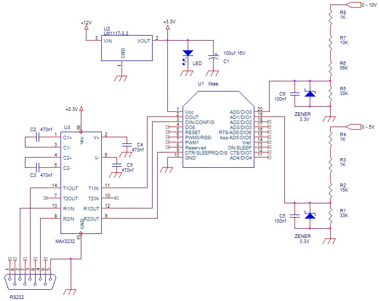
Analyzing the electric diagram, we can see that very few components are needed beside the Xbee module:
A voltage regulator LM1117-3.3 (U2) needed to regulate at 3.3V the power supply voltage for the wireless module;
A MAX3232 (U3) needed to adapt the module to the PC COM port used for configuration.
The ADC lines of the Xbee module can measure analog voltages up to a maximum of 3.3.V,
so in the above electric diagram two resistive partitors have been added designed for measuring upper voltage of +5V and +10V respectively.
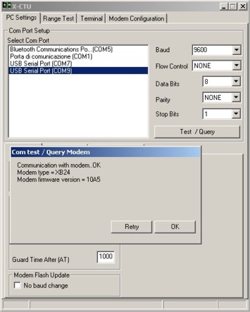
The configuration of the Xbee module has to be performed by mean of a PC where the software X-CTU is running
(it is available in the download section at the end of this article) connected with a serial cable to the node itself.
Once launched the tool X-CTU, you have to select the COM port of the PC where is connected the Xbee module
and then click the button "Test / Query" to verify if the link is good.
After this phase, we can go ahead to the section "Modem Configuration"
where it is possible to set all the parameters form ZigBee module operation.
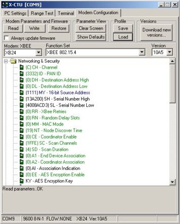
The configuration to be set to let the Xbee module work as described in this article is the following one:
CH=C
ID=3332
DH=0
DL=0 #Destination node address
MY=1111 #Node address (it must be different for each node)
EE=0
NI= TEST NODO
AP=1 #Api enabled
D8=0 #Input line not configured
D7=0
D6=3 #Input line configured as input
D5=2 #Input line configured as ADC
D4=2
D3=2
D2=2
D1=2
D0=2
IU=1
IT=1
IC=0
IR=1770 #Transmission every each 6 sec (1770hex == 6000 dec )
Once saved the configuration by clicking on the "Write" button,
the wireless module will start reading in a completely automatic way the voltages applied
on D0 and D1 lines with regular time intervals of 6 seconds,
then it will send them the receiving module with address 0000hex.
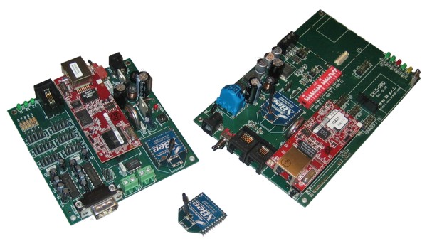
Realization and configuration of the central unit
The central unit, that receives and displays on a Web page the measures collected from the remote nodes,
may be realized with one of the SX3000EVO or SX15PRO boards where a Rabbit RCM3700 or RCM3710 processor
and a Xbee or XbeePRO (serie 1) module have to be mounted.
In the download section, two firmware samples are available:
FW_XBEE_SX15PRO and FW_XBEE_SX3000EVO are realized to be uploaded by mean of the RFU utility
on the RCM3700 module mounted over a SX15PRO board and SX3000EVO board respectively.
 If the SX15PRO board is used, you have to configure ON the two switches of the E serial port labelled with "XBEE" 
Once completed the firmware upload, we can restart the Rbbit module.
To verify the correct operation of the system, we have to connect a PC to the Rabbit module over the LAN
and open an Internet browser toward the address http://192.168.0.176.
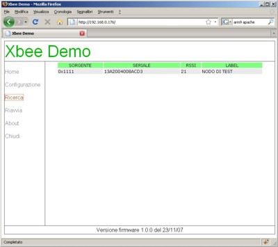
After few instants, we should see the following Web page displayed in the browser:
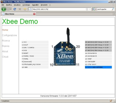
For each transmission from the remote node, the sent data packet is analyzed by the application running on the Rabbit module
and the result is displayed ond the Web page just described.
The Xbee module inputs configured as ADC will be displayed in gray colour while the ones configured as simple TTL will be displayed in blue colour.
By clicking on the link "Configuration", you enter the setup page.
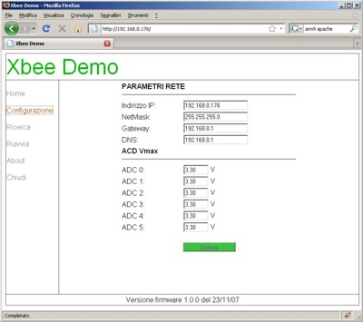
In this section, you can change the IP address where the Rabbit embedded web server responds but also you can set,
input by input, the voltage highest value to be measured
(Maximum value of voltage to be applied to the input, resistive partitor included).
From the link "Search" you can enter a web page that, after 30 seconds more or less, will show all the Xbee modules found in the coverage area.
Link
Site X-CTU Digi
Site Xbee Digi
Article: The Xbee and Xbee Pro modules: the wireless Zigbee transmissions made easy
Article: SX15-PRO the latest evolution for the RCM3700 control board
Article: SX3000EVO: a complete motherboard for the cheap and powerful RCM3700 processor
Download
 Software X-CTU setup_x-ctu.zip Software X-CTU setup_x-ctu.zip
Software RFU rfu.zip
Firmware for SX3000EVO FW_XBEE_SX3000EVO
Firmware for SX15PRO FW_XBEE_SX15PRO
Datasheet Xbee manual_xb_oem-rf-modules_802.15.4.pdf
Segnala questo articolo:
Tags: - Domotica - Schede Area SX - Telecontrollo - ZigBee -
| 


 Articles


 Area SX store
 Click here to request a quote for quantities above 5 pieces