In this section we will introduce a brief HOW-TO guide that, with the aid of
electric schematics and test source code, will give the guidelines to start
developing with FOX and SX18 boards. In particular for the second one,
the way to interact with the different peripheral devices will be explained.
HOW-TO guide summary
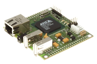
FOX board is a very small device (only 66 x 72 mm), based on ETRAX LX100 MCM 4+16 microprocessor produced by Axis,
on which a complete Linux System (with WEB server, FTP, SSH, etc.) runs.
Besides an 10/100 Base/T Ethernet interface and two USB 1.1 master ports, FOX board is equipped with two 20x2
and 2.54mm pins connectors where 62 I/O lines, one I2C bus port and three asynchronous serial ports take place.
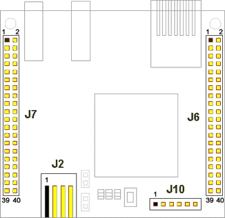
The complete pinout, needed to use FOX board, is shown in following table.
| J7 |
| Pin |
Dir |
Function |
Axis ref |
| 1 |
|
GND |
|
| 2 |
|
GND |
|
| 3 |
I/O |
IOG22 |
H18 |
| 4 |
I/O |
IOG23 |
H19 |
| 5 |
I/O |
IOG20 |
G19 |
| 6 |
I/O |
IOG21 |
G20 |
| 7 |
I/O |
IOG18 |
F19 |
| 8 |
I/O |
IOG19 |
G18 |
| 9 |
I/O |
IOG16 |
G17 |
| 10 |
I/O |
IOG17 |
E20 |
| 11 |
|
N.A. |
J17 |
|
12 |
|
N.A. |
C19 |
|
13 |
O |
OG25 |
A20 |
|
14 |
|
N.A. |
C20 |
|
15 |
|
N.A. |
B20 |
|
16 |
|
N.A. |
C18 |
|
17 |
|
N.A. |
E18 |
|
18 |
|
N.A. |
D19 |
|
19 |
|
N.A. |
E17 |
|
20 |
|
N.A. |
D20 |
|
21 |
I/O |
IOG24 |
E19 |
|
22 |
O |
I2C_RES |
N18 |
|
23 |
|
N.A. |
W20 |
|
24 |
|
N.A. |
C8 |
|
25 |
|
N.A. |
U19 |
|
26 |
|
N.A. |
T17 |
|
27 |
|
N.A. |
Y10 |
|
28 |
|
N.A. |
V19 |
|
29 |
|
+5V |
|
|
30 |
I |
IRQ |
U9 |
|
31 |
I |
DCD2 |
U7 |
|
32 |
I |
DSR2 |
V6 |
|
33 |
I |
RI2 |
Y5 |
|
34 |
O |
DTR2 |
W5 |
|
35 |
O |
DL1 |
Y4 |
|
36 |
O |
DL2 |
Y3 |
|
37 |
I |
SW1 |
U5 |
|
38 |
I/O |
PA0 |
W1 |
|
39 |
|
+3.3V |
|
|
40 |
|
+3.3V |
|
|
|
|
|
J2 |
|
Pin |
Dir |
Function |
Axis ref |
|
1 |
|
N.C. |
|
|
2 |
|
GND |
|
|
3 |
|
GND |
|
|
4 |
|
+5V |
|
|
|
|
J10 |
|
Pin |
Dir |
Function |
Axis ref |
|
1 |
|
+3.3V |
|
|
2 |
O |
RTS1 |
|
|
3 |
O |
TXD1 |
|
|
4 |
I |
RXD1 |
|
|
5 |
I |
CTS1 |
|
|
6 |
|
GND |
|
|
|
|
|
J6 |
|
Pin |
Dir |
Function |
Axis ref |
|
1 |
|
+3.3V |
|
|
2 |
|
+3.3V |
|
|
3 |
O |
RTS3 |
B19 |
|
4 |
I |
RXD3 |
J18 |
|
5 |
O |
TXD3 |
H20 |
|
6 |
I |
CTS3 |
J19 |
|
7 |
O |
RTS2 |
P19 |
|
8 |
I |
RXD2 |
J20 |
|
9 |
O |
TXD2 |
K19 |
|
10 |
I |
CTS2 |
K18 |
|
11 |
I |
NMI |
A18 |
|
12 |
|
+5V |
|
|
13 |
I/O |
IOG9 |
L18 |
|
14 |
I/O |
IOG8 |
L20 |
|
15 |
I/O |
IOG11 |
M19 |
|
16 |
I/O |
IOG10 |
L19 |
|
17 |
I/O |
IOG13 |
M17 |
|
18 |
I/O |
IOG12 |
M18 |
|
19 |
I/O |
IOG15 |
N19 |
|
20 |
I/O |
IOG14 |
N20 |
|
21 |
O |
OG2 |
K20 |
|
22 |
O |
OG5 |
P17 |
|
23 |
O |
OG1 |
P20 |
|
24 |
I |
IG1 |
R18 |
|
25 |
O |
OG4 |
R19 |
|
26 |
O |
OG3 |
R20 |
|
27 |
I |
IG4 |
T18 |
|
28 |
I |
IG3 |
T19 |
|
29 |
I |
IG2 |
T20 |
|
30 |
I |
IG5 |
V20 |
|
31 |
O |
I2C_CLK |
W16 |
|
32 |
I/O |
I2C_DATA |
V15 |
|
33 |
|
N.A. |
V16 |
|
34 |
|
N.A. |
Y17 |
|
35 |
|
N.A. |
Y18 |
|
36 |
I/O |
PB4 |
W17 |
|
37 |
I/O |
PB7 |
U16 |
|
38 |
I/O |
PB6 |
Y19 |
|
39 |
|
GND |
|
|
40 |
|
GND |
|
|
|
|
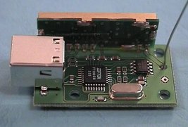
SX18 board is an hardware designed to allow projects realization using FOX board
with no need of external circuit or wired connection for power supply or peripheral devices.
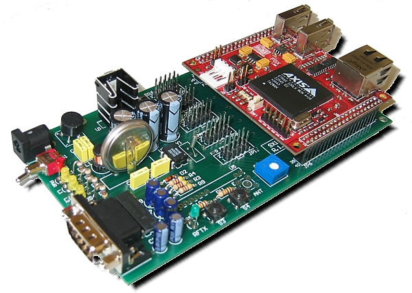
In a 150 x 80 mm board you find:
- 1 RS232 serial port placed on a panel connector
- An ER400TRS radio transceiver module connector (for further information: Trasmissioni in Radiofrequenza facili con Easy Radio)
- A Real Time Clock DS1302 chip with Lithium backup battery
- 2 test buttons
- 3 general purpose LEDs
- 1 power supply LED
- 3 general purpose 5+5 expander connectors
- 1 expander connector that is suitable for Input/Output SX16 board (for further information: SX16B - IN/OUT expansion board)
- 1 expander connector that is suitable for dimmer SX13 board (for further information: Multifunctions dimmer)
- 1 expander connector that is suitable for connection to an LCD display
Besides the peripheral devices just described, SX18 board is equipped with a large voltage range
power supply section that allows to feed the device with an ordinary power adapter 220V - 12V.
Complete SX18 electric schematic: SX18_Schematic.pdf
Main FOX programming language is C. Source cods, that may be written with any ordinary text editor,
have to be compiled with the appropriate SDK, at the moment available only for Linux and downloadable
for free from Axis Website at the URL:
http://developer.axis.com/download/compiler/old/
Or alternatively using the WebCompiler at the URL:
http://www.acmesystems.it/?page=webcompiler.
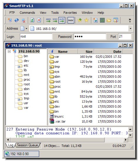
The file.out that is realized at the compilation end, may be uploaded in RAM or
FLASH memory of FOX board through an ordinary FTP client , opening a session toward the IP address
assigned to device (default 192.168.0.90) and using username root and
password acme.
To store the program in RAM, you have to move the file.out via FTP in the directory
/var/state.
Using this path, you may test your program but as soon as the board is powered off,
uploaded files will be deleted . To save the program in FLASH memory, you have to move
the file.out via FTP in the directory /mnt/flash/. This way file are saved also
when the board is turned off.
Once file upload is completed, to run the programs you have to open a Telnet Console or SSH
(you may use as Client program
Putty if you are using a Windows machine)
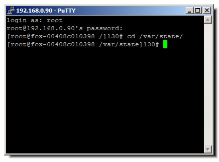
you have to enter the folder where the program has been uploaded
e.g.:
cd /var/state
and you have to make the file executable with the following command:
chmod +x program.out
Now you can launch you example typing before the executable program name "./"
./programma.out
On SX18 board there are three general purpose LEDs: DS2, DS3 e DS4 are connected
respectively to pins 13 (OG25), 21 (OG0) and 38(PA0) that are on FOX J7 connector.
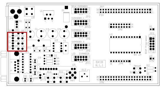
An easy test source code example follows: it initializes the ports and then makes
the three LEDs blink one after the other.
#include "stdio.h"

#include "unistd.h"

#include "sys/ioctl.h"

#include "fcntl.h"

#include "time.h"

#include "asm/etraxgpio.h"


#define LED_1  1<<25

#define LED_2  1<<24

#define LED_3  1<<0

#define IO_SETGET_OUTPUT  0x13


int main(void) {
  int fda;
  int fdg;
  int iomask_a;
  int iomask_b;
  int iomask_g;
  int i;


  if ((fda = open("/dev/gpioa", O_RDWR))<0) {
    printf("ERROR opening /dev/gpioa\n");
    return 1;
  }
  if ((fdg = open("/dev/gpiog", O_RDWR))<0) {
    printf("ERROR opening /dev/gpiog\n");
    return 1;
  }
  iomask_a = LED_3;
  ioctl(fda, _IO(ETRAXGPIO_IOCTYPE, IO_SETGET_OUTPUT),&iomask_a);
  iomask_g = LED_1 | LED_2;
  ioctl(fdg, _IO(ETRAXGPIO_IOCTYPE, IO_SETGET_OUTPUT),&iomask_g);


while (1) {
    printf("Test LED\n");
    ioctl(fdg, _IO(ETRAXGPIO_IOCTYPE, IO_SETBITS),LED_1);  //LED 1 ON
    sleep(1);
    ioctl(fdg, _IO(ETRAXGPIO_IOCTYPE, IO_CLRBITS),LED_1);  //LED 1 OFF
    sleep(1);
    ioctl(fdg, _IO(ETRAXGPIO_IOCTYPE, IO_SETBITS),LED_2);
    sleep(1);
    ioctl(fdg, _IO(ETRAXGPIO_IOCTYPE, IO_CLRBITS),LED_2);
    sleep(1);
    ioctl(fda, _IO(ETRAXGPIO_IOCTYPE, IO_SETBITS),LED_3);
    sleep(1);
    ioctl(fda, _IO(ETRAXGPIO_IOCTYPE, IO_CLRBITS),LED_3);
    sleep(1);
  }


  close(fda);
  close(fdg);
  return 0;
}
Two test buttons S3 and S4 are connected to FOX J6 connector pins 29 (IG2) and 28 (IG3).
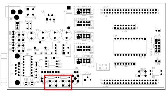
An easy buttons test source code example follows:
Each time one of these two buttons is pressed, then a message that says which one has been closed,
appears on console.
#include "stdio.h"
#include "unistd.h"
#include "sys/ioctl.h"
#include "fcntl.h"
#include "time.h"
#include "asm/etraxgpio.h"


#define BUTTON_1  1<<2
#define BUTTON_2  1<<3
#define IO_SETGET_INPUT   0x12


int main(void) {
  int fdg;
  int iomask_g;
  unsigned char value = 0;


  if ((fdg = open("/dev/gpiog", O_RDWR))<0) {
    printf("ERROR opening /dev/gpiog\n");
    return 1;
  }

  iomask_g = BUTTON_1 | BUTTON_2;
  ioctl(fdg, _IO(ETRAXGPIO_IOCTYPE, IO_SETGET_INPUT),&iomask_g);


 while(1) {
    value=ioctl(fdg, _IO(ETRAXGPIO_IOCTYPE, IO_READBITS));
    if ((value&(BUTTON_2))==0)
      printf("Button 1 pressed\n");
    if ((value&(BUTTON_1))==0)
      printf("Button 2 pressed\n");
  }
}
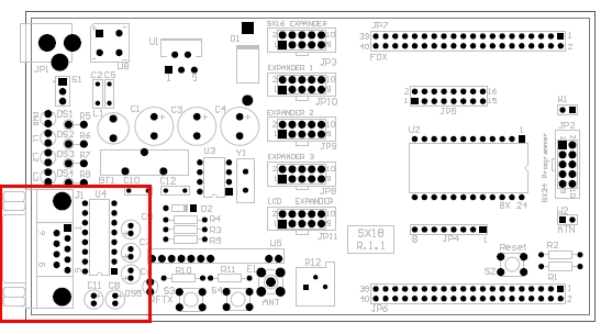
On SX18 there is a complete RS232 section composed by a
MAX232
(integrated chip for level translation from TTL/CMOS to RS232) and a 9 pins DB male connector.
Besides the standard RX and TX signals, on the connector there are also the flow control pins RTS and CTS.
RS232 serial section is connected to the FOX J6 connector pins 3 (RTS), 4 (RX), 5 (TX)
and 6 (CTS) and it is identified as /dev/ttyS3.
To execute serial port test, you need to connect SX18 board to a PC
using a serial cross cable. Its schematic is depicted in the following image:
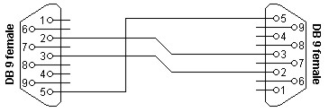
This kind of cable is needed because the FOX-SX18 pair is configured as DTE
(Data Terminal Equipment) that is the same for a PC in a serial link.
The proposed test source code is a simple ECHO program that sends back on the serial port
all the data coming from it. The source code is only an example that explains how to establish
a simple serial communication with FOX serial ports, in this particular case with ttyS3.
#include <stdio.h>
#include <string.h>
#include <unistd.h>
#include <fcntl.h>
#include <termios.h>
#include <sys/types.h>
#include <sys/stat.h>
#include <signal.h>
#include <stdlib.h>


#define BAUDRATE B19200
#define DEVICE "/dev/ttyS3"


int main (int argc, char * argv[]) {
  int fd, res;
  struct termios oldtio,newtio;
  char buf[200];
  printf("Opening Port COM\n");
  fd = open(DEVICE, O_RDWR | O_NOCTTY);
  if (fd < 0 ) {
    printf("Device %s unavailable on this system\n\n", DEVICE);
    exit(-1);
  }
  printf("Serial communication initialization\n");


  tcgetattr(fd,&oldtio); /* Save previous settings */


  bzero(&newtio, sizeof(newtio));
  newtio.c_cflag = BAUDRATE | CS8 | CLOCAL | CREAD;
  newtio.c_iflag = IGNPAR;
  newtio.c_oflag = 0;
  newtio.c_lflag = 0;
  newtio.c_cc[VTIME] = 0;
  newtio.c_cc[VMIN] = 1;

  tcflush(fd, TCIFLUSH);
  tcsetattr(fd,TCSANOW,&newtio);
  //Serial device
initialization finished

  sprintf(buf, "Hello, I'm FOX board equipped with SX18 :)\n\r Write, I'm listening (Type Q to quit)\n\r");
  if (write(fd, buf, strlen(buf)) < 0) {
    printf("DATA SENDING ON SERIAL PORT FAILED\n");
  }
  while(1){
    res = read(fd,buf,sizeof(buf));
    buf[res]=0;

    if (write(fd, buf, strlen(buf)) < 0) {
      printf("DATA SENDING ON SERIAL PORT FAILED\n");
    }
    if (buf[0]=='Q') break;
  }
  printf("\nClosing serial communication...\n");
  tcsetattr(fd,TCSANOW,&oldtio);
  printf("Bye :)\n");
  close(fd);
  exit(0);
}
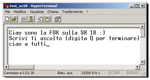
To test the communication you need to: connect the FOX SX18 pair to a PC using a serial crossed cable
(as described above); open a serial console on the PC (e.g. Hyperterminal or Minicom) and another console
SSH towards FOX to launch TEST_SERIALE.C. OUT application (file that is obtained compiling the above source code)
previously uploaded in FOX memory.
Now all the data typed on serial console will appear again on it after being processed by FOX board.
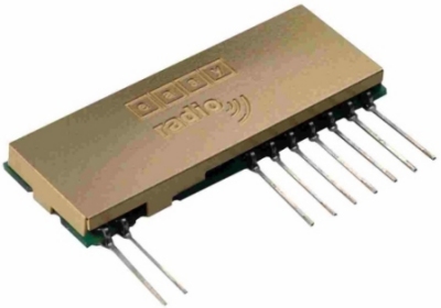
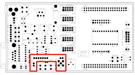
SX18 board may be optionally equipped with an Easy Radio ER400TRS radio transceiver
module suitable for serial data radio transmission. This module allows to establish a reliable wireless serial link.
ER400TRS module has already on boards all the functions for radio transmission: error control codes,
retransmissions management, power control, etc.
RF serial section is connected to the FOX J6 connector pins 8 (RXD) and 9 (TXD)
and it is identified as /dev/ttyS2.
RF serial link may be used to drive
SX16-RF
a complete I/O wireless expansion board, or to connect directly via RF the SX18 board to a PC equipped with
USBRF04 module.
The source code to test the SX18 RF peripheral device is the same used for RS232 section testing,
you only need to modify the define DEVICE this way:
#define DEVICE "/dev/ttyS2"
When serial data is passing through the RF link, RFTX led will blink.
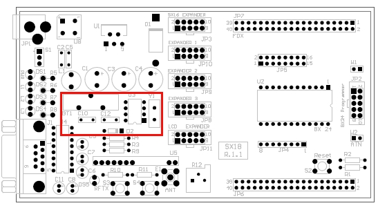
SX18 board is equipped with a Dallas RTC
DS1302 with its own backup battery, fully supported by FOX kernel.
RTC is needed to keep stored exact date and time on FOX system also when power supply is removed.
To set time and date, launch the date command with the following syntax:
date MMDDHHmmYYYY
where:
MM is the month from 01 to 12
DD is the day from 01 to 31
HH is the time (hours) from 00 to 24
mm is the time (minutes) from 00 to 59
YYYY is the year
e.g.:
date 051813502005
To save permanently the settings in RTC chip and let the system reload
them at each start, you need to launch the command
hwclock -w
If you want to display the FOX stored date, you only need to launch from console the command
date
The 10 pins SX18 connector named "SX16 EXPANDER" has been designed for straight
connection of a SX16-BASE to FOX board.
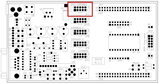
This particular SX16 configuration, even if with the same I/O equipment,
is much cheaper since it isn't equipped with PIC and Easy Radio ER400TRS module.
Hardware configuration:
- 24 inputs divided as
8 direct inputs TTL level
(0V-5V)
8 filtered inputs (CLC filter) TTL level (0V-5V)
8 Optocoupled inputs for input voltage up to 24V DC,
eventually configurable as TTL level inputs (0V-5V)
- 6 relays output that allow to drive voltage up to 125V (30W load)
- 1 temperature sensor DS1621 with ½ C° accuracy and -55 a + 128°C range
SX16-BASE is the ideal solution to realize a complete I/O peripheral for your own microprocessor
using only few control lines.
SX16 expander is connected to FOX pins according to the schema depicted in the following table:
| FOX |
SX16 EXPANDER on SX18 |
|
JP2 on SX16-BASE |
| PB6 (pin 38-J6) |
pin 1 |
<-> |
SDA (pin 1) |
| PB7 (pin 37-J6) |
pin 2 |
--> |
SCL (pin 2) |
| OG3 (pin 26-J6) |
pin 3 |
--> |
ICL (pin 3) |
| IG1 (pin 24-J6) |
pin 4 |
<-- |
IDA (pin 4) |
| OG5 (pin 22-J6) |
pin 5 |
--> |
IPL (pin 5) |
| OG1 (pin 23-J6) |
pin 6 |
--> |
OCL (pin 6) |
| OG4 (pin 25-J6) |
pin 7 |
--> |
STR (pin 7) |
| OG2 (pin 21-J6) |
pin 8 |
--> |
ODA (pin 8) |
| VCC +5V |
pin 9 |
--- |
VCC +5V (pin 9) |
| GND |
pin 10 |
--- |
GND (pin 10) |
The source code to test the several SX16 sections is described in the following article:
Controllare la SX16-BASE dalla FOX board
The connector named "LCD EXPANDER" has been designed to connect easily
and quickly a Hitachi HD44780 interface LCD display to FOX board.
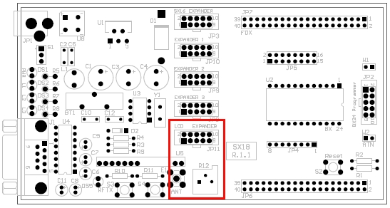
On the 10 pins JP11 connector, besides the display power supply, you will find also a
trimmer (R12) needed for contrast control.
FOX pins connected to LCD expander are described in the following table:
| FOX |
ESPANDER LCD on SX18 |
LCD |
| IOG8 (pin 14-J6) |
pin 1 |
D0 |
| IOG9 (pin 13-J6) |
pin 2 |
D1 |
| IOG10 (pin 16-J6) |
pin 3 |
D2 |
| IOG11 (pin 15-J6) |
pin 4 |
D3 |
| IOG12 (pin 18-J6) |
pin 5 |
RS |
| IOG13 (pin 17-J6) |
pin 6 |
EN |
| IOG14 (pin 20-J6) |
pin 7 |
BL |
| Trimmer R12 |
pin 8 |
|
| VCC +5V |
pin 9 |
VCC |
| GND |
pin 10 |
GND |
Examples for LCD display control are available at the following link:
http://www.acmesystems.it/?id=8021
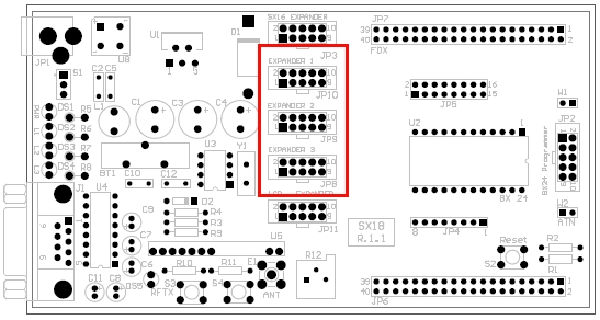
The three 10 pins (5+5) SX18 expander connector named JP8, JP9 and JP10 are available
for the user and they are connected to FOX pins according to the schema described in the following three tables:
EXPANDER JP8
|
FOX |
EXPANDER JP8 on SX18 |
| IOG8 (pin 14-J6) |
pin 1 |
| IOG9 (pin 13-J6) |
pin 2 |
| IOG10 (pin 16-J6) |
pin 3 |
| IOG11 (pin 15-J6) |
pin 4 |
| IOG12 (pin 18-J6) |
pin 5 |
| IOG13 (pin 17-J6) |
pin 6 |
| IOG14 (pin 20-J6) |
pin 7 |
| IOG15 (pin 19-J6) |
pin 8 |
| VCC +5V |
pin 9 |
| GND |
pin 10 |
EXPANDER JP9
|
FOX |
EXPANDER JP9 on SX18 |
| IOG16 (pin 9-J7) |
pin 1 |
| IOG17 (pin 10-J7) |
pin 2 |
| IOG18 (pin 7-J7) |
pin 3 |
| IOG19 (pin 8-J7) |
pin 4 |
| IOG20 (pin 5-J7) |
pin 5 |
| IOG21 (pin 6-J7) |
pin 6 |
| IOG22 (pin 3-J7) |
pin 7 |
| IOG23 (pin 4-J7) |
pin 8 |
| VCC +5V |
pin 9 |
| GND |
pin 10 |
EXPANDER JP10
|
FOX |
EXPANDER JP9 on SX18 |
| TXD (pin 9-J6) |
pin 1 |
| RXD (pin 10-J9) |
pin 2 |
| IG2 (pin 29-J6) |
pin 3 |
| IG3 (pin 28-J6) |
pin 4 |
| IG4 (pin 27-J6) |
pin 5 |
| IG5 (pin 30-J6) |
pin 6 |
| IRQ (pin 30-J7) |
pin 7 |
| NMI (pin 11-J6) |
pin 8 |
| VCC +5V |
pin 9 |
| GND |
pin 10 |
For this board, the following items are available for downolad:
Segnala questo articolo:
Tags: - How-To - Linux - Schede Area SX -
| 


 Articles


 Area SX store


